Time for an update.
Been slow going over the last few weeks. And havent really achieved that much. Just minor things like free-ing up excess wieght out of the car where possible. Sorting out the problems with the brake pedal box / accelerator pedal mount. And then getting the fuel tank out, ready to be replaced with a race cell. And also removing the now obsolete spare wheel well. And little things like getting the bars going to the front strut towers more welded out. And patching holes in the firewall etc.
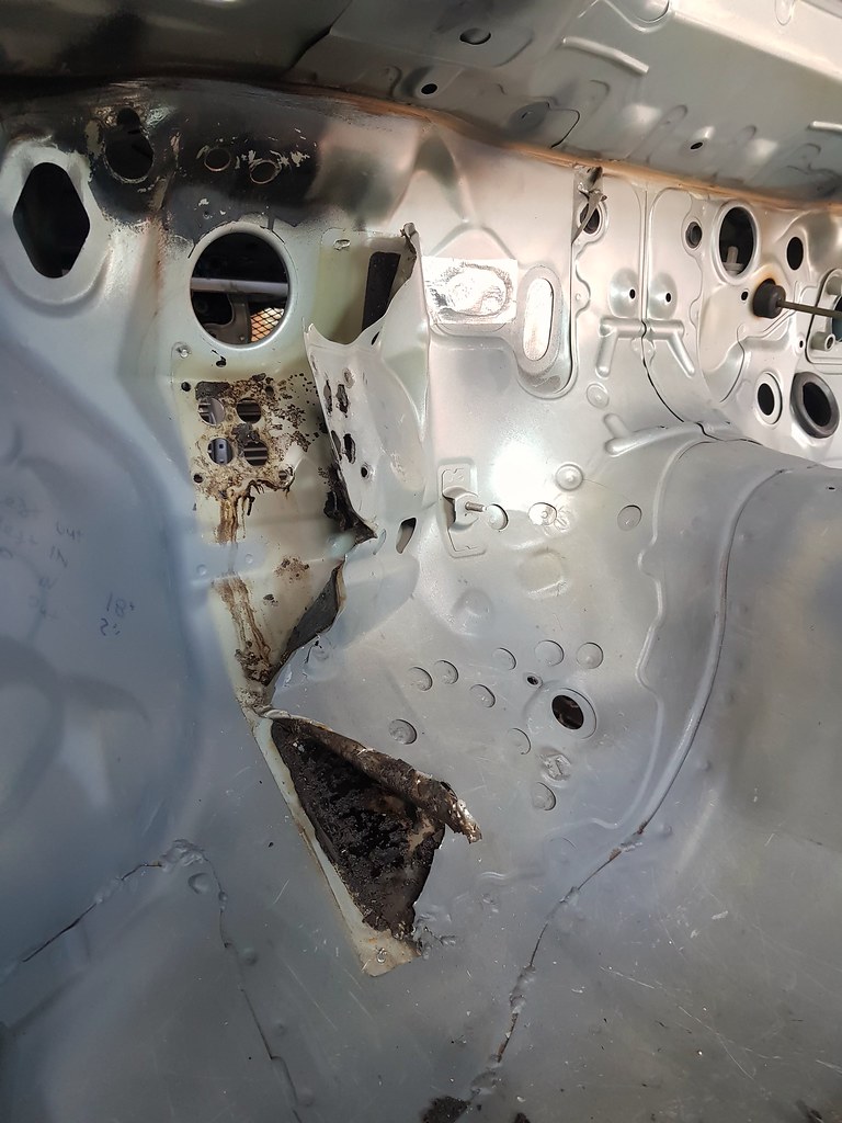
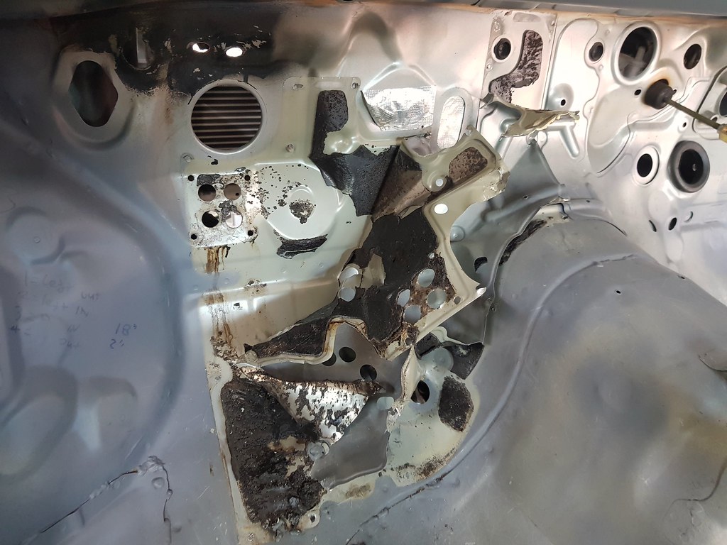
First up, i removed some of the additional insulation layers from the firewall, and rear strut towers. These are an interesting design, where they sandwhich a layer of bitumen based body deadener/insulation between a very very thin layer of sheet metal. Then spot weld it together. This is done on the firewall, the base of the gutter below the windscreen, and the inner sides of the rear strut towers. The sandwhiching layer of steel is very thin. It offeres practically no structure, other than to encapsulate the body deadener/insulation material. Its not that much thicker than al-foil to be honest. And you can literally peel it off by hand, pulling the spot welds apart.
The insulation under neath is very much like the inner body deadener they put over the floor pan areas. But maybe a bit more moist still. (Possibly because its been protected by the sheet metal?) The only thing I can think the sheet metal is there to do is to prevent the bitumen from being a fire risk. Bitumen based material is kinda flammable if its heated and ignited. Or maybe they do it on the vertical sections where they want the sound deadener??? All the other locations that they use the bitumen based deadener is all horizontal or close to. The sections on the firewall and strut towers are vertical, so perhaps that is why they are sandwiched with the super thin sheetmetal, to keep the bitumen in place.
Its hard to get an exaxt amount of wieght, as the insulation kinda falls apart as you remove it. But i estimate i have removed about 2 to 2.5KGs from the firewall, and about 1.5 to 2kgs from the rear strut towers. Not massive savings, but it adds up if you do enough bits and pieces around the car.
 2019-03-03_07-23-12
 by
bram biesiekierski, on Flickr
 2019-03-03_07-23-24
 by
bram biesiekierski, on Flickr
 2019-03-03_07-23-35
 by
bram biesiekierski, on Flickr
While i was there, i patched over a number of the unused holes in the firewall. For example the old heater hose and AC pipe holes. The fuel pipe pass-through The holes i put in for the hydro handbrake etc. Just trying to tidy it up and make it an actual fire proof firewall. Only left a couple of holes for the new wiring loom to lass through.
Next I sorted out the troublesome CompBrake pedal mechanism. I reinforced the balance bar tube. I cleaned the old paint out of the balance bar tube, so the balance bar bearing actually slides inside it. I also slightly kinked the lever, to get the pedal in a better location. And also cut off the foot plate, and welded it on at a better angle. The angle it came at was no where like the angle the standard pedals hang at.
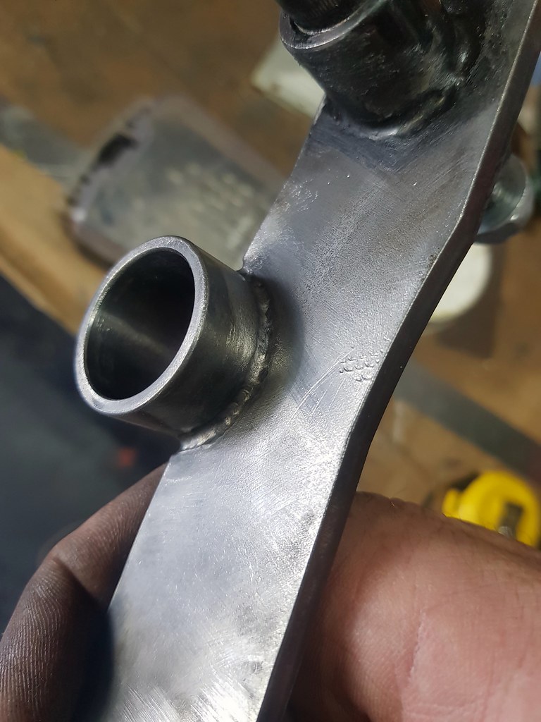
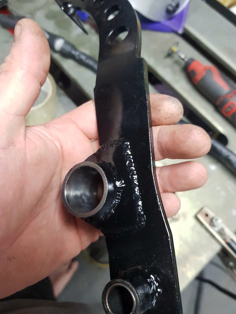
This photo shows how much weld is connecting the brake pedal to the master cylinders as it comes from CompBrake. If this fails and pulls away from the lever. You have ZERO brakes. It would probably be alright. But i didnt trust it fully. I dont like the idea that the tube is welded onto the side of the brake pedal lever. The balance bar tube should be fully entrapped in the brake pedal lever, meaning its virtually impossible to break free. Because safety.
 2019-03-03_07-22-42
 by
bram biesiekierski, on Flickr
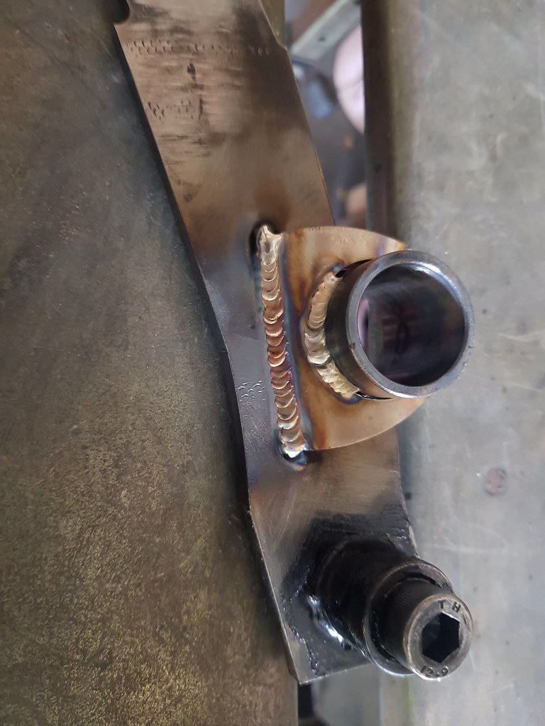
So I added 2 additional bits of steel that fully encapsulate the balance bar tube. And i fully welded them in. I left the original weld as is. And only added the additional bracing and welds to add to it.
 2019-03-03_07-22-55
 by
bram biesiekierski, on Flickr
 2019-03-03_09-53-25
 by
bram biesiekierski, on Flickr
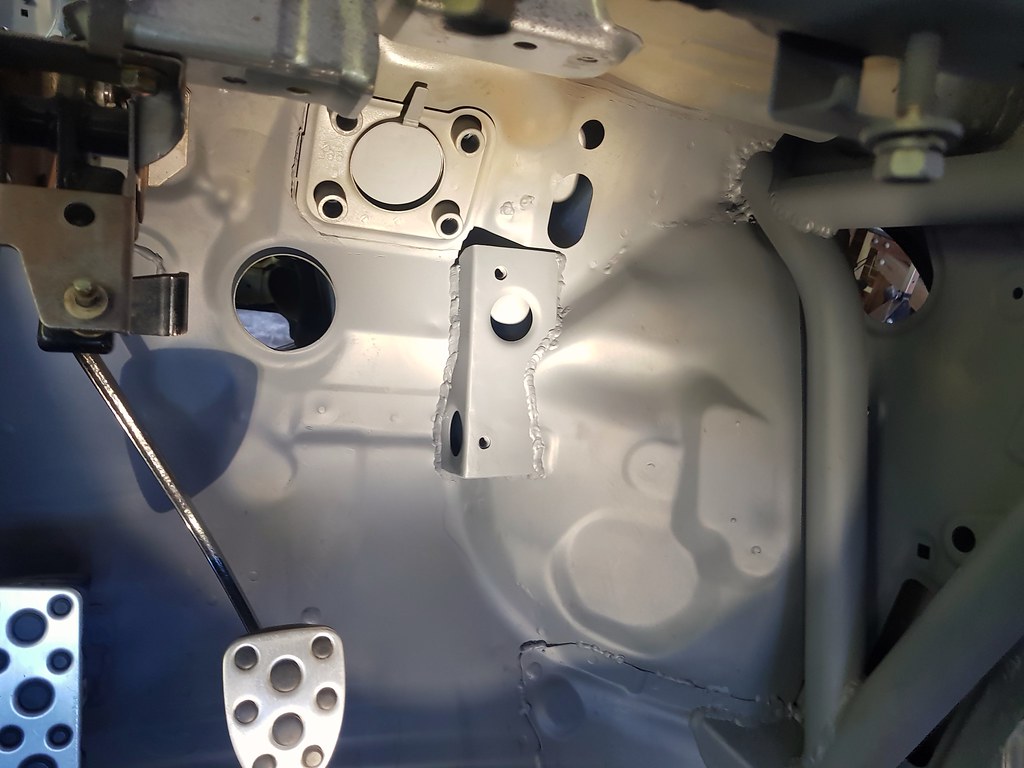
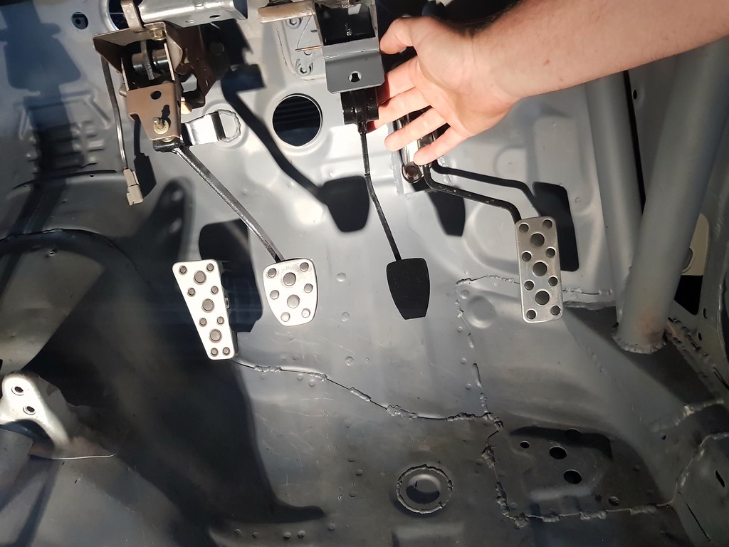
I also cut off the old accelerator pedal sensor mount. And fabricated up a new box section plate to shift it over 20mm away from the brake mechanism. The new acc pedal mount is alot more ridgid than the OEM part. And most importanly, it clears the brake pedal box. I carefully bent and tweaked the accelerator pedal lever/rod to kinda get the actual pedal back over to the OEM location. So although the pedal sensor is shifted over to clear the brake mechanism, the actual pedal itself is more or less in the correct position.
 2019-03-03_07-22-09
 by
bram biesiekierski, on Flickr
 2019-03-03_09-52-32
 by
bram biesiekierski, on Flickr
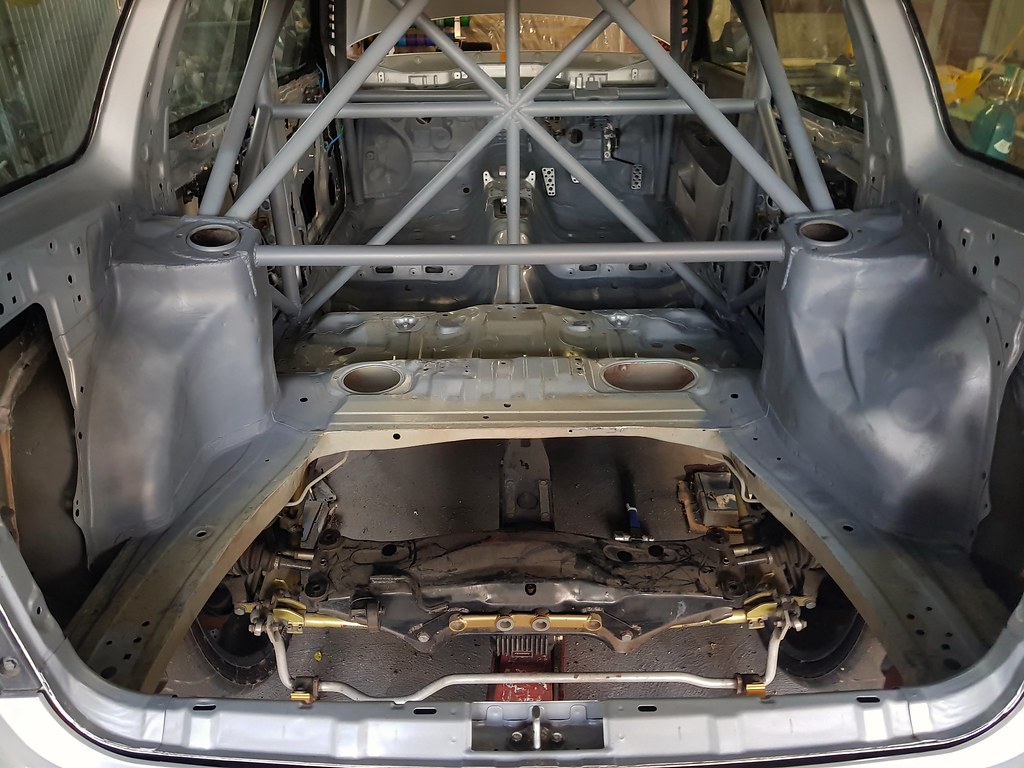
Next up was to remove the spare wheel well. This one had been on my mind for along time. The well is pretty heavy, as it needs to support the spare wheel. And when you run 295 wide tyres, it kinda doesnt even fit a wheel in there anymore. So out came the jigsaw and the angle grinder.
I also dropped the exhaust and then dropped the rear cradle, diff, shafts, hubs, wheels, brakes, suspension and swaybars as an entire unit, so I could then remove the OEM fuel tank. The OEM tank is a saddle bag sort of thing that actually humps over the rear diff. So that needs to drop to allow the tank to get free. The entire rear end comes out with a handfull of bolts. Just drop it as a complete assembly. Didnt even need to remove the wheels.
 2019-03-03_07-21-06
 by
bram biesiekierski, on Flickr
I have an ATL 12 gallon (30L) 600 series kevlar/fluro-polymer fuel cell to go in.
ATL is the sole supplier to F1 for thier fuel bladders. And also many other top level motorsports teams/series use ATL cells. I was hoping it would arrive this week, but looks like it will be here on tuesday. (Public holiday monday) So making it fit will be next weeks job. The obvious place to put it is directly behind the rear diff. But the cell is actually small enough to fit on the drivers side of the OEM location. It small enough to fit between the tailshaft/diff/diff out-rigger and rear suspension arms / trailing arms. But it needs part of the floor cut out where the rear seat area bulges in to get enough vertical hieght. So putting it there is an option too. I could also put it on the passenger side of the OEM tank location aswell. This would be better for wieght distribution. But the exhaust would interfere, and need to be modified. (Side pipes anyone???) So not 100% on mounting location yet until it arrives and I have a feel for it.
The fuel cell is entirely filled with special foam baffling inside to prevent fuel slosh. The fluoro kevlar bladder is housed in an aluminum box. The box is super thin, and just supports the bladders shape. Its 0.060" which is about 1.5mm thick. The crash puncture / tear strength of the cell is all handled by the actual kevlar bladder itself. And the box just gives you something to mount it to and keep the bladders shape. The cell wieghs 10 US pounds. Which is about 4.5kgs. (About 1/5th of the standard tank) It also is 30 L, so stores about 1/2 the volume of fuel as the OEM tank. Which means 1/2 the wieght of a standard fill.
On top of the cell i have ordered a radium FCST. Which is basically a surge tank that can be integrated inside the fuel cell. It has a lift pump, and up to 3 main pumps. (I opted for 3 X walbro F90000267. 1 lift, 2 x main) And it is all housed into the actual lid of the fuel cell. Meaning you cut down on plumbing between cell and surge tank. And can support multiple pumps, again, all internally connected without additional external plumbing.
The new cell will be a direct fill for now. Meaning it has a cap on the actual cell, instead of a pipe like the standard setup. So i removed and blocked off the old fill hole.
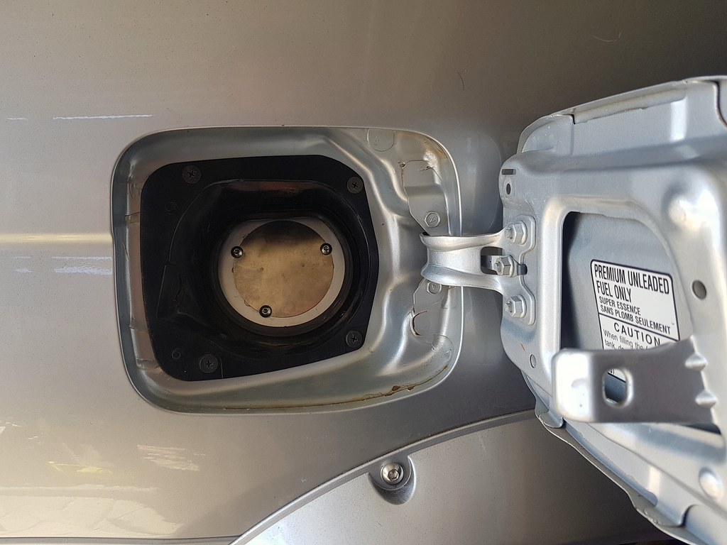 2019-03-03_07-20-56
 by
bram biesiekierski, on Flickr